Racecar Telemetry System
The goal of this project is to collect operating data from a racecar and transmit it wirelessly to the pitlane for real-time review. The most important information to collect is the car's fuel consumption, as the system is used in endurance racing. This project consists mainly of making a PCB which collects car data and sends it to a 900MHz band radio. From this project I made my first PCB and learned about digital communication like CAN and UART.
For context on this project, my family has a 1994 Miata modified to do amateur endurance races between 7 and 24 hours in length. It is extremely useful to know how much fuel the car has left in it, and we can do that by knowing how much fuel the car starts each stint with and its fuel consumption through the stint. The car will run for about two hours on a single tank.
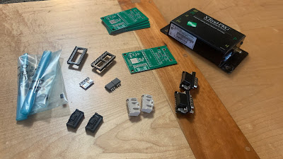
I started this project with two radios, Digi XTend PKG in the 900MHz band. They are Spread Spectrum Frequency Hopping with lots of cool features, but most importantly I am able to configure them to act like a wireless cable. In fact, setup consisted of only setting DIP switches on each unit and plugging things in. Easy.
I started with breadboard circuits to verify that I could read CAN data from the car's ECU and that I could effectively parse it with a microcontroller. I chose the Teensy 4.0 to do this as it has a CAN controller and is fast. I also tested sending data from the Teensy to one of the radios and receiving it on my computer, which was successful. Arguably the hardest part made simple.
Another important circuit is the optocoupler. An accurate way of measuring fuel consumption is to measure the total amount of time the fuel injectors are open and flowing, which I use an optocoupler for. The injectors run on 12V with the possibility of flyback voltage, so an optocoupler is a good option for complete isolation of the 'high' voltage. The other consideration in this decision is reliability. If something fails, I don't want to take down the fuel injection circuit which would force the car to stop.
I used EasyEDA to design the board, it's free and wasn't hard to learn.
The car has an ECU which outputs CAN data, and there are various analog sensors which go to a CAN capable datalogger onboard as well. The majority of the data comes from CAN, but I also made sure to connect some analog input pins on the Teensy to the 20 pin board connector so I could later add an analog sensor if desired.
The last thing I did was to 3D print an enclosure from ABS and install everything in the car. I ran an antenna wire to the trunk of the car where the radio's antenna mounts and wired the 20 pin male connector into the car's harness.
Here is the firmware/arduino code for the Teensy, using interrupts to detect when the fuel injector fires or a CAN message is received. Data is sent to the serial port in each loop iteration, and the delay slows the loop time to give the desired data rate but importantly does not block the serial port or the interrupts from functioning.
Here is the link to the related data visualization project for displaying the data in real-time in the pits.


